This page draws product references from the supplied catalogue. Stated ranges are for initial discussion; final capacity, materials, utilities and performance must be confirmed in the technical proposal and project agreement.
What this screw press is designed to do
This product family is positioned for the sludge line rather than the water line. Its job is to receive a defined sludge feed, create a stable flocculated mass, separate released liquid and deliver a more manageable cake for transfer, storage or off-site disposal. In a complete industrial wastewater project, that role connects directly to disposal logistics, space planning and the reliability of the upstream clarification or biological process.
Process logic and working principle
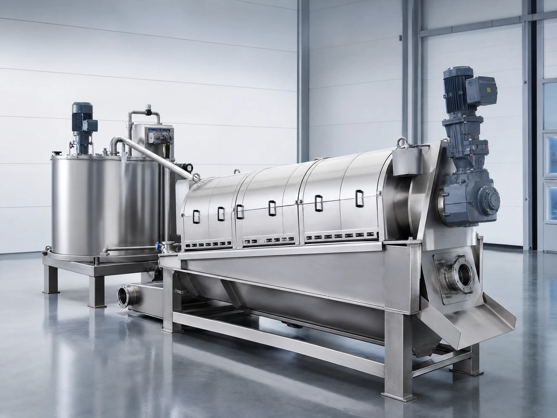
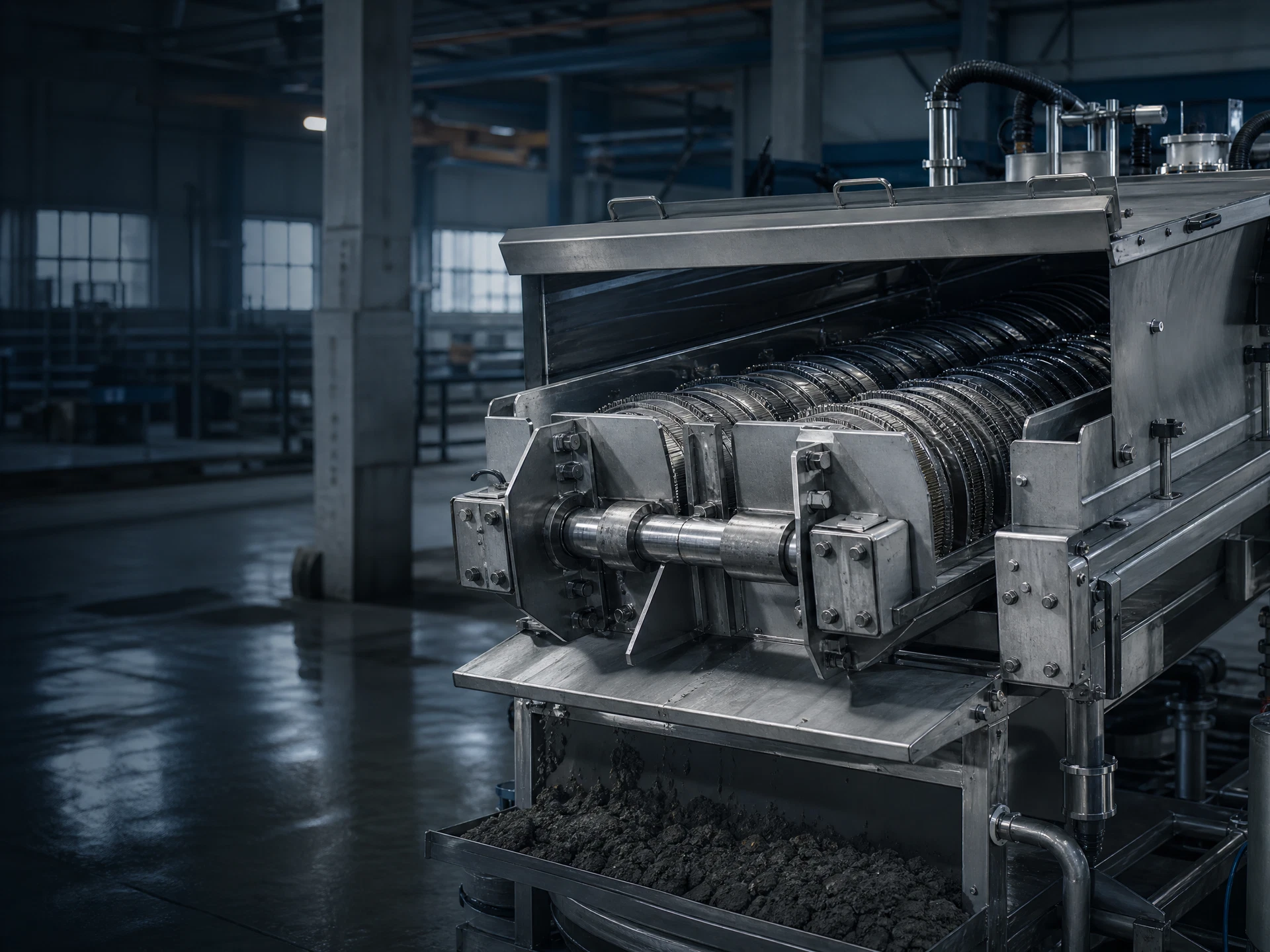
The supplied catalogue describes an integrated sequence of a metering zone, flocculation mixing zone, screw body, fixed and moving ring assembly, cake discharge plate and integrated electrical control. Conditioned sludge travels through the ring-stack section while the screw creates progressive conveying and compression. Filtrate is released through the ring gaps and the retained solids are moved toward the discharge end. The process is continuous, but its outcome remains dependent on the feed sludge, polymer choice and the operating set points selected for the project.
Configuration should follow the actual duty
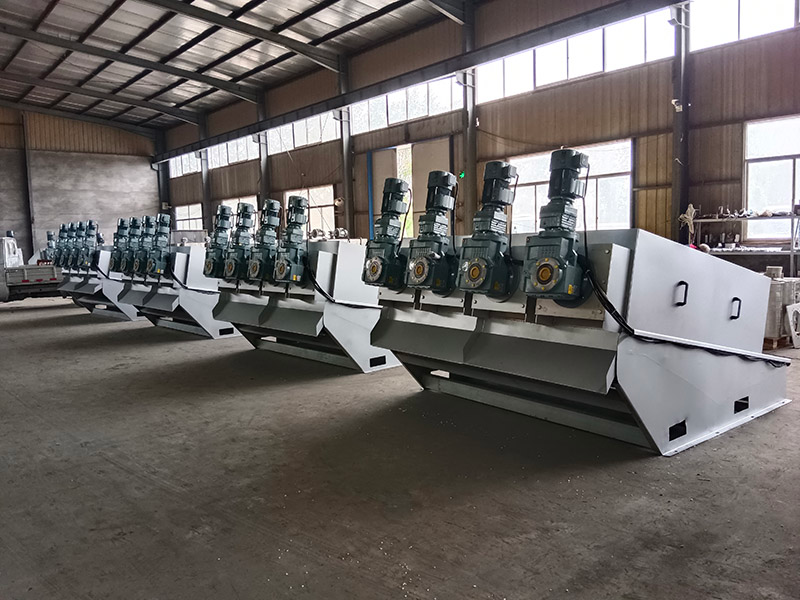
The catalogue presents the SMDL series from SMDL131 to SMDL403, with screw-body arrangements ranging from approximately φ130 × 1 to φ400 × 3. A buyer should treat that series structure as the starting point for capacity screening, not as a substitute for an agreed design basis. The machine may be considered together with upstream polymer preparation, feed pumping, filtrate routing, cake conveyance and local control interfaces so that the sludge line functions as a complete operating package.
A disciplined route to model selection
Initial selection should begin with measured dry-solids production, average and peak feed concentration, the variability of the sludge, the presence of abrasive grit or long fibres, available operating hours and the requested destination for dewatered cake. A water-flow number alone is not a sufficient basis because the same volume of liquid can contain very different solids loads. The expected cake condition, polymer programme, wash-water availability, installation access and service arrangement should also be recorded before confirming a model.
Connecting the unit to the wider treatment line
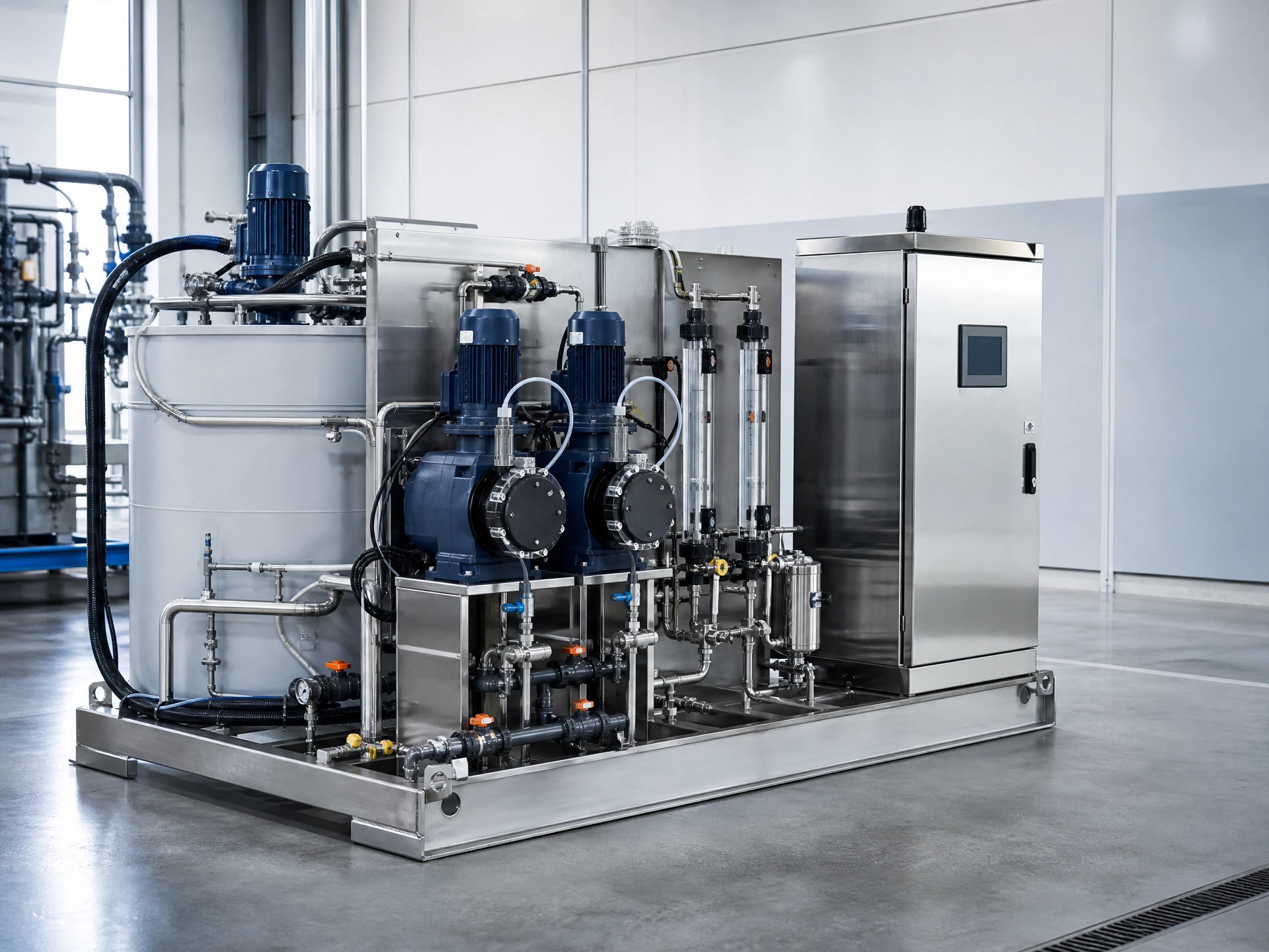
For a typical industrial installation, the screw press follows sludge collection or thickening and is supplied by a polymer dosing step. The resulting cake can be directed to a shaftless screw conveyor or sludge hopper. This sequence keeps wet sludge handling, polymer conditioning and solids transfer within a visible operational chain. The control philosophy should define permissives between feed, dosing, mixing, dewatering and downstream cake removal so that one stalled unit does not create an uncontrolled overflow condition.
Operating attention and maintenance context
The brochure identifies low-pressure wash-water operation as a design feature and lists a reference washing-pressure range of approximately 0.1–0.2 MPa. Practical operating routines should still be based on the actual sludge behaviour. Sticky biological solids, fibrous material and abrasive inorganic solids can change the cleaning interval, wear pattern and polymer demand. Operators should trend feed concentration, floc appearance, filtrate clarity, cake condition and motor load to identify changes before they become a maintenance event.
How performance should be validated
No generic website statement can guarantee cake dryness, polymer consumption, filtrate solids, throughput or maintenance interval for every sludge. The supplied catalogue provides model ranges and reference operating values; final project values should be confirmed through wastewater and sludge characterization, where appropriate bench testing, a defined scope of supply and a technical agreement. This evidence-led approach is particularly important where disposal cost, limited space or strict plant availability makes the dewatering outcome commercially significant.
A practical engineering review before RFQ
A technically complete request for screw press equipment should combine process data, mechanical layout data and operating expectations. Process data explains the material or water to be handled; layout data identifies access, elevation, utilities and interfaces; operating expectations identify automation level, service approach and the desired response to an upset. This information allows an equipment proposal to move from a nominal catalogue comparison to a configuration that can be reviewed by the project engineer. It is also the right point to identify what remains to be confirmed through sampling, site survey or a technical clarification. Where several products are supplied together, the package should define responsibility for every hand-off, including feed, dosing, drainage, discharge and control signals. The goal is not to make a proposal needlessly complex. It is to make the scope visible enough that the final equipment can be installed, started and maintained with the intended process role intact.
Installation planning and physical interfaces
An equipment proposal is only complete when the physical installation is understood as well as the process duty. The project team should check the receiving floor or channel arrangement, lifting access, maintenance clearance, feed and discharge elevations, drainage paths, utility connections, local isolators and the route by which components reach the final location. Screw Press equipment must also be considered in relation to the machines before and after it. A carefully selected unit can still be difficult to operate if a transition chute blocks, a service door cannot open, a wash-water line is inaccessible or the downstream transfer path has no capacity. General arrangement drawings and interface schedules should therefore be reviewed early, particularly for retrofit sites. The intended sequence for transport, placement, installation, testing and commissioning should be coordinated with the plant programme. Any site responsibilities that remain outside the equipment scope should be stated explicitly so the installation plan does not depend on assumptions made by different contractors.
Controls, alarms and normal operating decisions
Automation is valuable when it makes the equipment state visible and establishes a predictable response to normal variations. The final control package should identify the relevant local controls, field signals, alarms, interlocks and connections to the plant control system. For example, a material feed condition, a low level, a high level, motor overload, poor downstream availability or a utility interruption may each require a different response. The correct logic cannot be standardized without reference to the project, because the risk of stopping a machine depends on the process around it. During technical clarification, discuss the electrical supply, desired local and remote modes, operator interface language, required feedback signals, emergency-stop philosophy, alarm reporting and responsibilities for any plant-level PLC integration. A concise cause-and-effect schedule makes these expectations readable. It also helps commissioning teams test the intended safeguards in a controlled way rather than discovering control gaps after the equipment enters service.
Operating continuity and lifecycle attention
Equipment value is achieved over the operating period, not only on the delivery date. The project specification should consider routine inspection access, cleaning provisions, normal wear parts, safe isolation, spare-parts planning and the practical skills available at the site. The relevant inspection points differ by product, but the operating principle is consistent: observe the unit while it is stable, establish normal operating indicators, and investigate meaningful changes in sound, vibration, load, leakage, material behaviour or outlet condition. A plant that records these observations can plan maintenance before a minor change affects the wider treatment line. This does not require a claim that the equipment will run without attention; it requires a realistic service strategy. When evaluating alternatives, compare the total operating arrangement, including access and interface design, rather than comparing a single catalogue power figure or an unsupported generic maintenance statement. The project documentation should specify exactly which recommended spares, manuals and support arrangements apply to the ordered configuration.
Responsible use of catalogue information
Catalogue data is essential for early screening because it allows project teams to identify families, approximate size ranges and expected configuration questions. It is not a replacement for the final design basis. The values displayed on this page are therefore presented with their source context: where the supplied catalogue states a range, the range is shown; where the catalogue does not state a universal value, the website says that the point must be confirmed. This protects decision quality and avoids creating a misleading appearance of precision. Before issuing a purchase order, the buyer should make sure that the approved proposal records the selected model, capacity basis, utility requirements, materials, dimensions, interfaces, control scope, documents and performance-validation method. That record becomes the reliable source for procurement, installation and acceptance. It is the difference between a useful product page and an unsupported promise.
Document control, scope clarity and responsible claims
Industrial wastewater equipment is evaluated against operating consequences, not only headline dimensions. For that reason, the most useful commercial documents state the supplied equipment boundary, the selected model, the utilities required, the interfaces excluded or included, the controls offered and the assumptions behind any capacity statement. Screw Press proposals should separate brochure reference data from project-confirmed design values. They should also identify which parameters are to be checked after review of wastewater or solids data. This approach protects the buyer and supplier alike: it makes it easier to compare alternatives, it prevents a reference range from being mistaken for a universal guarantee and it establishes a clear agenda for technical clarification. Once the final inputs are agreed, drawings, electrical information and operating guidance can be aligned with the actual job rather than with an assumed generic installation.
From enquiry to an informed technical proposal
The next step is an RFQ that describes the site in engineering terms. Include the country and industry, expected operating schedule, project stage, flow or solids quantity, major pollutants or material characteristics, target outcome and any known utility constraints. Photographs, layout sketches and laboratory information can help a technical team identify the most relevant questions quickly. Shandong Shengmai Environmental Protection Technology Co., Ltd can use that information to structure a product discussion around the supplied catalogue range and the intended process interface. Before purchase, the final technical specification should record the assumptions that matter most: capacity basis, materials, instrumentation, electrical supply, installation limitations, documentation, commissioning support and the performance-verification method. That disciplined sequence gives every page of this website a practical purpose: helping an international project team collect the facts needed for a credible equipment decision.